Technical Walkthrough
How It Works
From first sensor mount to first alert — typically under 10 days. No machine downtime required for installation.
Four-Step Process
Install to insight in under 10 days
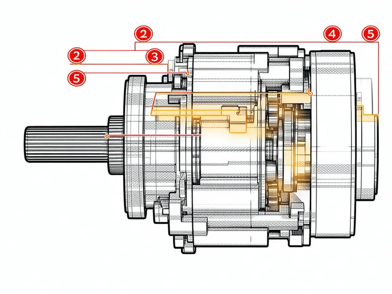
Clip-on accelerometers attach to bearing housings without removing guards or stopping machines. Current clamps go around motor leads. Thermocouples clip or bolt to housings. All sensor types use standard DIN rail DAQ hardware or connect to your existing OPC-UA historian. Target: one shift to instrument 2–4 machines.
Gearcadence connects to your sensor streams via OPC-UA, Modbus TCP, or MQTT — whichever is already running. Over 5–7 days, the system learns normal operating signatures for each machine at each RPM range and load condition. Baseline captures: vibration spectrum envelope, thermal steady-state, current draw at nominal load.
After baseline, continuous ML inference compares incoming sensor data against the learned normal envelope. Bearing defect frequencies (BPFO, BPFI, BSF, FTF), gear mesh frequency sidebands, and envelope-demodulated impulse energy are evaluated on every data window. No alarm setpoints to configure — the model flags what deviates.
Prioritised alerts appear in the Gearcadence dashboard and route to your maintenance team via webhook, SAP PM notification, email, or SMS. Each alert includes: fault type, affected component, confidence level, estimated time-to-failure range, and recommended action. Maintenance planners can acknowledge, snooze, or escalate in the dashboard.
What you need before you start
We don't need your CMMS credentials or ERP access to deploy the monitoring layer. Work order output integration is configured after the pilot phase, not before it.
Equipment Coverage
Equipment classes with proven detection signatures
Talk to an engineer about your equipment.
Lukas or a team engineer will walk your floor specs with you before you commit to a pilot.